|
|
|
|
DESIGN TWO MULTIPLEXERS
AND TEST IT on A UP-2 BOARD.
Please follow the example that you had in the lab.
1. Specification 1
- The output from the multiplexer is 10 bit bus named " Result_Full_10bit"
- The inputs to the multiplexer are 4 signed integer constants , Each constant is 10 bit word with values 1, -2,3,4. See the diagram below.
- The control bus is named "Unsigned 4BitSELECT"
- The control waveform is generated by a counter named "Incerament Decrement". It generates a step waveform with increaments of one.

|
|
|
|
|
The required waveforms are given below. The multiplexer control waveform is " Unsigned Integer 4bit". The output waveform is "Result_Full_10bit".
Please note that the output waveform is periodic with period 4! PLease explain !

2. Specification 2.

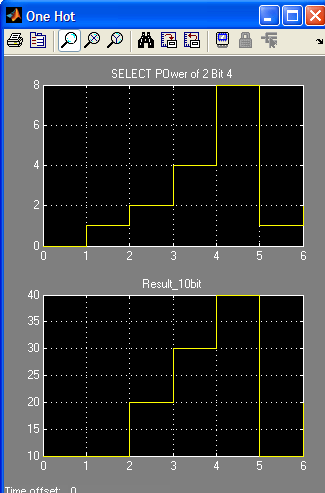
In this case the control waveform is a sequence of 4 4-bit packets. Each 4-bit packet is an unsigned power of 2 integer =1,2,4,8.
The inputs to the multiplexer are also indexed as powers of two numbers.
The first input is a 10-bit integer with unsigned value 10 and is applied to MUX input 1.
The second input is a10-bit integer with unsigned value 20 and is applied to MUX input 2.
The third input is a10-bit integer with unsigned value 30 and is applied to MUX input 4.
The fourth input is a10-bit integer with unsigned value 40 and is applied to MUX input 8.
The required waveform ant the output of this MUX is given below:


